This study is also in .pdf format if that works better for you.
Skid Tests
on a
Select Group of Bicycle Helmets
to Determine Their
Head-Neck Protective Characteristics
Voigt R. Hodgson, Ph.D.
Director Gurdjian-Lissner Biomechanics Laboratory
Department of Neurosurgery
Wayne State University
Detroit, Michigan
This report was prepared in cooperation with the
Michigan Bicycle Helmet Advisory Committee
and the Michigan Department of Public Health
The study was partially funded for $25,000 through an Injury Control Incentive Grant (R49/CCR 503309-2) to the Michigan Department of Public Health from the U.S. Department of Health and Human Services, Public Health Service, Centers for Disease Control. The conclusions are those of the author and do not necessarily reflect the policy or views of the Centers for Disease Control.
Additional support was provided by Wayne State University Neurotrauma Prevention Fund
Wayne State University
Department of Neurological Surgery
550 E. Canfield
Detroit, Michigan 48202
March 8, 1991
Abstract
A select group of bicycle helmets, representative of hard shell, micro-shell and noshell with either rubber straps or nylon cover models, were subjected to skid-type impacts to smooth and rough concrete inclined at five angles from 30 to 60 degrees. Impact occurred in the range of 6.5-8.5 mph (10.4-13.7 km/hr), the upper limit of which was dictated by risk of damage to the neck transducer in the modified Hybrid III dummy. Two dummy body orientations at impact, both symmetrical to the sagittal plane, were investigated.Test results predict that hard and micro-shell helmets provide about equal protection from cervical spine injury. The hard and micro-shell helmets tended to slide rather than hang up on impact with concrete. This sliding tendency was the mechanism that reduced the potential for neck injury. Nylon covers on the no-shell helmets were helpful under some conditions in allowing sliding to occur as the cover was stripped off the helmet by friction with the concrete.
Under the test conditions, head injury risks from the standpoint of linear accelerations, were negligible in all cases. Rotational head motion did not approach dangerous levels of combined angular acceleration and angular velocity.
Because of rebounding onto the rubber dummy face after sliding impacts, several methods were used to save the face from abrasive contact with the concrete. A polycarbonate faceguard attached to a micro shell helmet not only saved the dummy face from being abraded, but reduced head-neck injury index measurements. It also assisted in keeping the helmet in place.
Results of this series of tests (and similar previous tests of the unhelmeted dummy), predict that any helmet similar to those used in these tests will protect the brain and neck much better than wearing no helmet.
page iv
Acknowledgments
Albert I. King was principal investigator the Centers for Disease Control project and this work was done at his suggestion and encouragement.Fernando G. Diaz, M.D., Ph.D., as chairman of the Department of Neurosurgery, keenly supported this research.
Ken Thompson helped devise the instrumentation to make the measurements and performed the computer operations necessary to produce this document.
Matthew Mason performed the still photography, and built the skid test setup.
Eugene Dupuis assisted in the instrumentation, mechanical setups and conduct of the tests.
Jack Thrush, Chief, Health Surveillance Section, Michigan Department of Public Health was instrumental in the support of this research program.
Patricia K. Smith, Consultant, Michigan Bicycle Helmet Project, MDPH, monitored progress and provided guidance for this work.
Table of Contents
Acknowledgments.......iii
Abstract.......iv
I. Introduction.......1
II. Test Procedures.......1
III. Results.......8
IV. Conclusions.......14
V. Recommendations.......16
VI. Comment.......17
VII. References.......17
Appendix.......19
Figure a: Rubber Strap Covered No-Shell Helmet Oscillogram.......20
Figure b: Nylon Covered No-Shell Helmet Oscillogram.......21
Figure c: Micro-Shell Helmet Oscillogram.......22
Figure d: Hard Shell Helmet Oscillogram.......23
Figure e: Micro-Shell Helmet with Faceguard Oscillogram.......24
Figure f: No-Shell v Hard Shell Helmet Oscillogram.......25
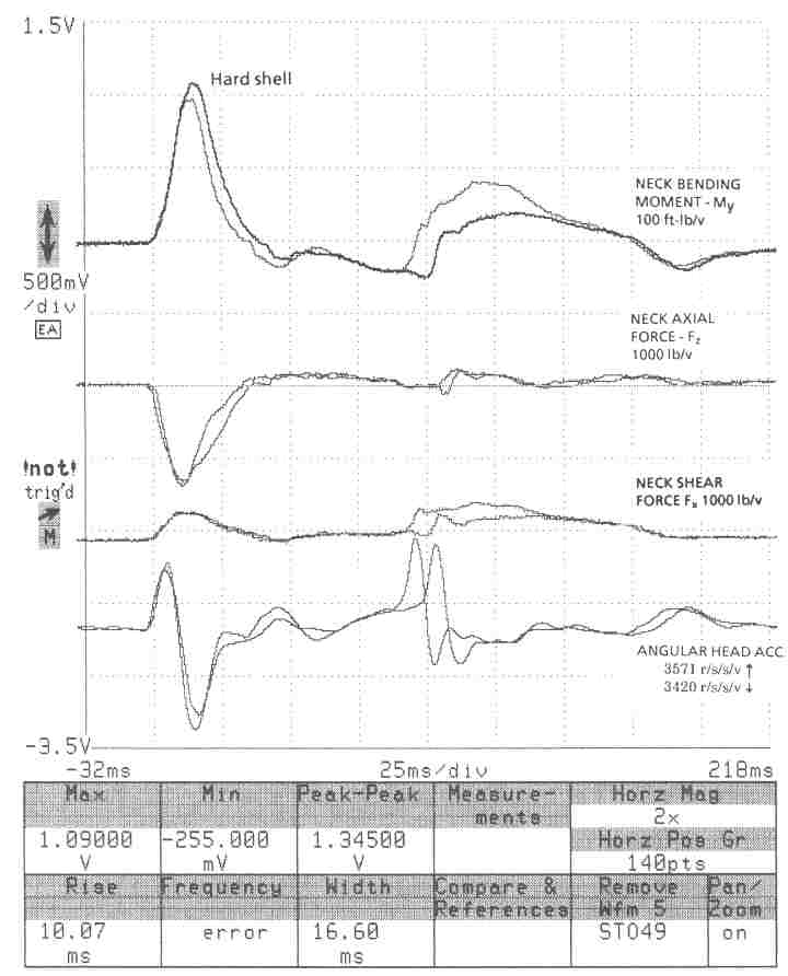
Figure g: Micro-Shell v Hard Shell Helmet Oscillogram.......26
Tables
Table 1: Peak values of all tests.......6
Table 2: Effect of neck-body orientation.......9
Table 3: Nylon v rubber strapped no-shell helmet.......11
Table 4: Effect of slab angle, rough concrete.......12
Table 5: Effect of faceguard on micro-shell helmet performance.......12
Table 6: Effect of velocity on head-neck loads.......13
Table 7: Effect of surface roughness.......15
Table 8: Effects of slab angle, smooth concrete.......15
Table 9: Comparison of grip angle for hard, micro-, and no-shell helmets.......16
Figures
Figure 1: Smooth concrete skid test setup....... 2
Figure 2: Rough concrete slab....... 3
Figure 3: Types of helmets tested....... 3
Figure 4: Micro-shell helmet with faceguard attached....... 4
Figure 5: Dummy body orientations at impact with 45 degrees angle slab.......5
Page v
Skid Tests on a Select Group of Bicycle
Helmets to Determine Their Head-Neck
Protective Characteristics
Voigt R. Hodgson, Ph.D.
1.Introduction
This study is an extension of a series of abbreviated skid tests conducted previously [Reference 1 at end]. The object of the current study was to investigate more thoroughly the relative risk of head, face and neck injury in bicycle helmets with various outer surfaces. Tests were conducted with a modified, full-sized Hybrid III Dummy instrumented with head-neck transducers. The dummy, while wearing one of six different bicycle helmets, was driven into one of two different textured slabs of concrete set at varying oblique angles (see Figure 1). The effect when a large component of tangential loading occurred was evaluated.The variables investigated were:
- SHELL: hard, micro or none
- SURFACE: smooth concrete, rough concrete
- SLAB ANGLES: 30 degrees-60 degrees; 7.5 degree increments
- SPEED-mph(km/hr): 6.5-8.5 (10.4-13.7)
- BODY ORIENTATION: 2
Hard shell helmets are typically eps molded liners covered by an injection molded shell made of a variety of thermoplastic substances, such as high density polyethylene, which vary in thickness between 0.062 in - 0.080 in (1.6 mm - 2.0 mm). This type of helmet construction is designed to make the molded liner relatively more impenetrable to sharp objects, more likely to hold together during a collision and to skid on impact surfaces. Typically, the no-shell, micro-shell, and hard shell helmet weights would be on the order of 0.42 lb, 0.56 lb, and 0.73-0.89 lb (1.9 N, 2.5 N, and 3.2 - 4.0 N), respectively.
11.Test Procedures
Instrumentation for these tests included a linear triaxial accelerometer mounted at the dummy head center of gravity; an accelerometer in the head to measure angular accelerations about an axis perpendicular to the mid-sagittal plane; and also a transducer to measure shear force, axial force and flexion-extension bending at the head-neck interface. A force transducer was mounted under the slab to measure the shear and perpendicular components of impact force. Figure 1 showspage 1
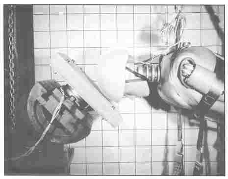 Figure 1: Bicycle helmet skid test setup with no-shell helmet mounted on the Hybrid III dummy in position to contact a smooth concrete slab attached to a force transducer. The dummy was driven horizontally at the slab, which was set at various angles between 30 and 60 degrees.
the dummy in an orientation with the neck at 0 degrees and trunk at +17 degrees to the horizontal, about to strike the slab inclined at 45 degrees. The dummy had been reduced in weight to 130 lb (578 N) by removal of arms and legs.
In this phase of testing a rough surface was added (see Figure 2), and only five helmet models, representative of hard shell, micro-shell and no-shell helmets with expanded polystyrene (eps) liners currently available on the market, were tested. Limited tests of a unique no-shell helmet with rubber straps, provided by the Bicycle Helmet Safety Institute, were also conducted. The six helmets used in this phase of testing were:
- Zephyr: no-shell eps with rubber straps on exterior surface
- LT-1100: no-shell eps with nylon cover
- LT-900: eps with micro-shell
- LT-950: nylon net impregnated eps with micro shell
- Troxel Comp Sx: eps with ABS hard shell
- Troxel Coronado: eps with polypropylene hard shell
These helmets are pictured in Figure 3. Several tests were also conducted with a faceguard attached to the LT-950 micro-shell helmet, as displayed in Figure 4.
Page 2
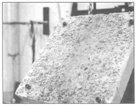
Figure 2: Rough concrete slab with small pebbles embedded into the surface
(see penny for size comparison to pebbles).
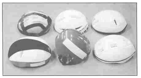 Figure 3. The six types of bicycle helmets used in this series of
tests include left to right: In the top row no-shell with attached
external rubber straps; hard shell; micro-shell. Bottom row:
no-shell with removable nylon cover, hard shell with
increased occipital coverage; micro-shell with embedded liner
net.
Figure 3. The six types of bicycle helmets used in this series of
tests include left to right: In the top row no-shell with attached
external rubber straps; hard shell; micro-shell. Bottom row:
no-shell with removable nylon cover, hard shell with
increased occipital coverage; micro-shell with embedded liner
net.
Page 3
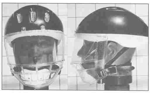 Figure 4. Micro-shell helmet with polycarbonate faceguard attached.
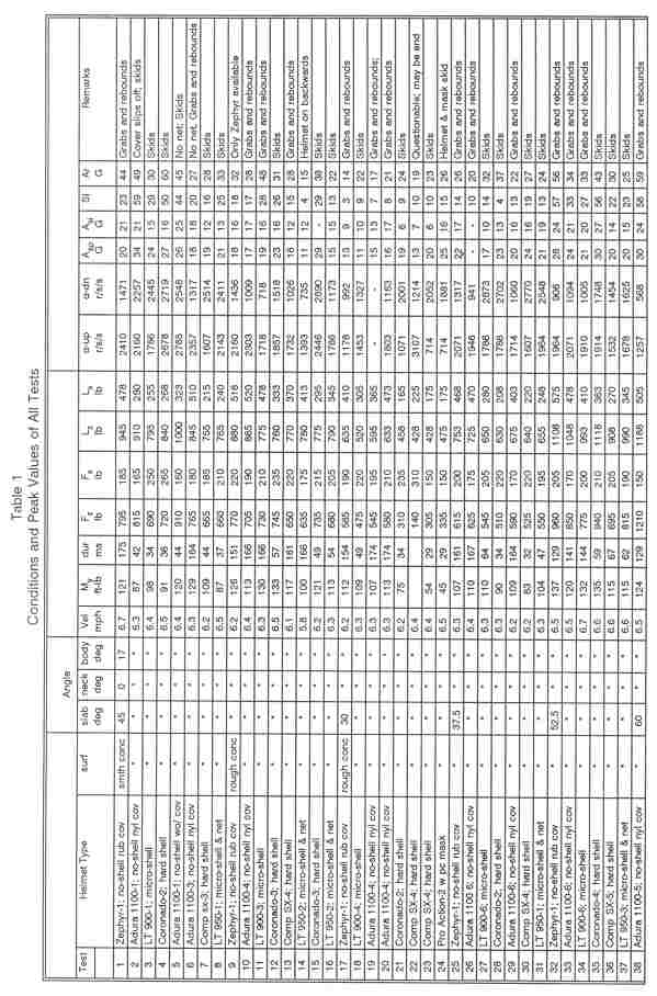
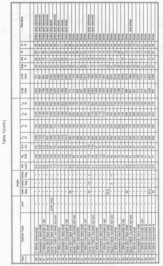
The order of tests and the test conditions are as presented in Table 1, columns 1-7. Nomenclature for the measurements, given in the tables as peak values, is as follows:
- velocity - average velocity through 1.00 in (25.40 mm)
spaced infra-red light beams across the path of the dummy within 1
in (25 mm) of impact. Units: mph= 1.609 km/hr.
- My - bending moment measured about a transverse (y) axis
at the head-neck junction of the Hybrid III dummy. Units: ft-lb=
1.356 N-m (Newton meter).
- force - lb=4.448 N (this conversion is also used for
weight, which is the force necessary to restrain a body against
free fall due to force of gravity).
- dur - duration of impact as measured in milli-sec (ms)
on the bending moment oscillogram.
- Fz - axial force measured in the neck of the dummy.
- Fx - shear force applied to the neck of the dummy in the
anterior-posterior direction (or vice versa).
- Lz - perpendicular force component applied to the
concrete slab by impact of the dummy.
- Lx - parallel to the slab surface force component.
- r - angular accelerations measured about a transverse
axis (y) in the dummy head. Units: radians/s/s.
- Aap - linear acceleration measured in the anterior-posterior (ap) direction in the dummy head. Units: G (acceleration due to force of gravity; at sea level G = 32.2 ft/s/s (9.8 m/s/s)).
- Asi - linear acceleration measured in the superior-inferior (is) direction in the dummy head.
- Severity Index (SI)[Footnote a below] - computed on the resultant head acceleration Ar of Aap and Asi.
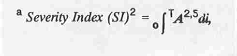
where T is effective impact duration.
A is instantaneous acceleration (G).
dt is time increment of integration.
A is instantaneous acceleration (G).
dt is time increment of integration.
Because of the limited space for the large amount of data given in some of the tables, data in all of the tables have been given only in U.S. units, instead of both U.S. and SI (International System) units as in the text, where the above conversion factors have been used.
Conduct of a typical test was as follows. After calibrating the ten measurement channels given in the nomenclature, the surface was selected as either the smooth concrete slab, judged to be typical of concrete roadways, or concrete with small pebbles--on the order of 1/4 in (6 mm) diameter--impregnated in the surface, representative of a rough, leached road surface. The surface was clamped at the desired angle between 30 degrees and 60 degrees, in 7.5 degree increments. The modified Hybrid III dummy was oriented in one of two angles of attack with the neck set in its maximum extended position. The most used body orientation was with the cervical spine horizontal, in which case the thoracic spine was at + 17 degrees to the horizontal. In the second orientation, the cervical spine was -15 degrees and the thoracic spine +2 degrees to the horizontal (see Figure 5).
The dummy was suspended from above and held in alignment below by seat belts attached to aluminum guide bars mounted on rollers, which ran in parallel overhead and floor tracks set in a vertical plane. A helmet was fastened snugly on the 7 1/8 sized dummy head, after fixing the slab inclination and body orientation
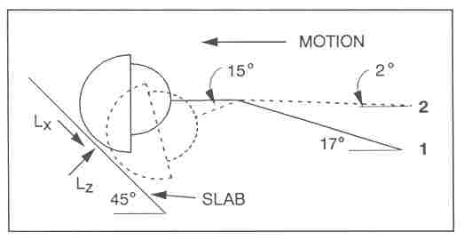 Figure 5. Dummy body orientations 1 and 2 at impact with a concrete
slab at 45 degrees.
Figure 5. Dummy body orientations 1 and 2 at impact with a concrete
slab at 45 degrees.
of the dummy. Attached to the upper bar was a tension spring which was pulled back by a winch to a selected position pre-determined to produce a velocity of near either 6.5 or 8.5 mph (10.4 or 13.7 km/hr) [Footnote a below].
Footnote a: In these types of tests, during which large tangential forces can act on the head when hang-up with the concrete occurs, the neck load transducer controls how extreme the environment can be allowed to become before forces and/or bending moments approach damage levels in the dummy. For these surfaces, angles and some helmets, damage levels to the dummy head-neck transducers were approached in this relatively low velocity range.
A quick release was actuated and the spring pulled the dummy to a point in close proximity to the slab, after which it was allowed to free wheel through a velocity-measuring, infra-red timing gate into forehead impact with the inclined concrete slab. Impact occurred in the range of 2.5 in (64 mm) to 6 in (152 mm) above the front rim of the helmet. If the helmet did not grab the concrete and rebound, the head of the dummy was free to slide up the length of the 15 in (380 mm) slab, shortly after which rubber bumpers on the tracks stopped the guide bars and subsequent tension on the suspension belts stopped the dummy.
III. Results
Peak Values of All Tests. Oscillograms of all tests were obtained. Peak values along with impulse duration, taken from the time the bending moment channel My left zero amplitude until return, were extracted electronically from the oscilloscope. They are tabulated in Table 1 along with conditions for each test. Figures a-d in the appendix illustrate the oscillograms for 6.5 mph (10.4 km/hr) impact to the smooth concrete slab inclined at 45 degrees for the rubber strap covered no-shell, nylon covered no-shell, micro-shell and hard shell helmets, respectively.To clarify the effects of the various conditions on neck loads and head accelerations, data were extracted from Table 1 and reassembled into Tables 2-8. Linear head accelerations (Aap, Asi, Ar) and Severity Indices (SI), indicators of potential for brain injury, were extremely low under these test conditions and consequently were not extracted from Table 1. It should be pointed out that they do not become significant under these types of skid impact simulations unless a helmet is not worn as demonstrated in the earlier study.
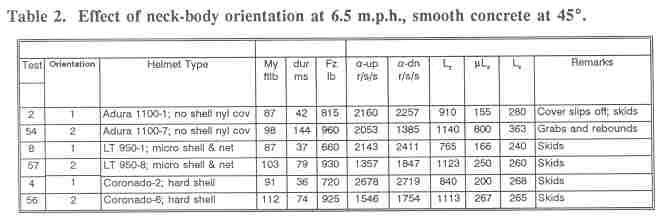
Effect of Neck-Body Orientation, for near 6.5 mph (10.4 km/hr) impacts to smooth concrete inclined at 45 degrees (see Table 2 for data). When the helmet on the dummy head strikes the smooth concrete slab as depicted in the Figure 5, the impulsive force acting on the helmet can be broken into two components--one perpendicular to the slab (Lz), and a component parallel to the surface (Lx). Assuming that the concrete was perfectly smooth, the maximum force of friction which could be developed is a Lz, where µ is the coefficient of sliding friction on the smooth concrete slab. This was determined experimentally from the tangent of the concrete ramp angle at which helmet sliding commences due to the force of gravity component along the ramp.
Page 8
Values of µ were found as follows:
    Helmet type        µ

    Hard shell        0.24
    Micro shell       0.22
    No-shell          0.70 (0.17 when sliding on its nylon cover)
With this information and the slab force component measurements, Lz and Lx, it is possible to obtain a better understanding of why the helmets skid or hang up on the smooth concrete slab. This information also helps clarify why, when the dummy's body orientation is switched from 1 to 2, the head and neck injury measurements change in the manner shown in Table 2.
The dummy strikes the slab more perpendicularly in body orientation 2 than 1. This causes the following changes, regardless of helmet type tested:
1. The perpendicular force component acting on the slab, Lz, increases and consequently µLz also increases.
2. Neck injury parameters My, Fz, and their duration all increase.
3. Head injury parameter alpha, decreases.
4. Parallel force component Lx, remains about the same for hard shell and micro-shell helmets, but increases in the no-shell helmet.
Because the concrete is not perfectly smooth, surface roughness is a factor in all three types of helmets, as was evident by the scratch marks on the helmet exteriors after all skid tests. It is for this reason that the parallel force component, Lx, measured on the force cell under the slab, is greater than the maximum friction force which could be developed if perfectly smooth surfaces of the same materials were impressed against each other.
In the case of the no-shell helmet, body orientation 1, the concrete surface penetrated into and hung onto the nylon cover and eps on the front, causing a momentary hang-up, forcing the neck into flexion. Because the nylon cover was not glued to the eps liner, the liner slid in the cover. The cover was caught on the concrete, pulling it off the rear of the liner. This provided a runway with less friction, allowing the head to skid and bounce, as is evident from the Lx oscillogram
 Page 9
trace in Figure b. The friction component dropped from 280 lb (1250 N) to sporadic amounts generally less than the 155 lb (690 N), calculated as maximum from using the eps-nylon coefficient of friction. During the skidding and bouncing phase of motion, the torque acting on the head, due to friction, was overcome by the internal torque in the dummy resisting flexion and the neck straightened to its equilibrium position.
Page 9
trace in Figure b. The friction component dropped from 280 lb (1250 N) to sporadic amounts generally less than the 155 lb (690 N), calculated as maximum from using the eps-nylon coefficient of friction. During the skidding and bouncing phase of motion, the torque acting on the head, due to friction, was overcome by the internal torque in the dummy resisting flexion and the neck straightened to its equilibrium position.
In body orientation 2, the perpendicular force component acting on the no-shell helmet was 25 percent higher than for orientation 1. This provided enough friction and gripping to prevent skidding and stripping of the cover, causing a rolling motion of the head. This forced the neck to remain in flexion until all the kinetic energy of the dummy (less the energy dissipated by friction and deformation) was absorbed, after which the dummy rebounded straight back from the slab horizontally.
Both the hard shell and micro-shell helmets, in body orientation 1, hung up momentarily and forced the dummy into neck flexion, followed by release into a straight neck. During tests of hard and micro-shell helmets with body orientation 2, there was an increase in perpendicular force components by 33% and 47%, respectively, over orientation 1. This phenomena doubled the time during which the neck compression-flexion was sustained, but still reached only about the half the 144 ms duration of the no-shell helmet. This situation occurred because there was not enough gripping action of the concrete on these slippery shells to develop much higher than the theoretical maximum, µLz, below which skidding would occur. Consequently, as the dummy kinetic energy was dissipated in time, the Lx force resisting skidding more quickly fell below the skid force level in the hard and micro-shell than for the no-shell helmet. In orientation 2, the no-shell helmet could have developed 800 lb (3560 N) to prevent skidding, compared to only 250-267 lb (1110-1190 N) for the slippery shells.
Angular accelerations were greater in body orientation 1 than in body orientation 2, which was more perpendicular to the slab. This was because leverage of the forces acting on the head to cause it to rotate, and their rate of application and release, decreases as the impact center moves toward the top of the helmet. In none of the six tests listed in Table 2, or any test listed in Table 1, was the 4500 r/s/s tolerance level and other criteria for parasagittal bridging vein rupture approached [Reference 3 at end].
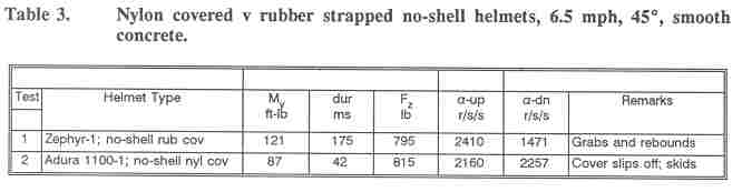
Nylon v Rubber Covered No-Shell Helmet, for 6.5 mph (10.4 km/hr), smooth concrete inclined at 45 degrees. The data in Table 3 show that whatever function exterior coverings serve, such as to provide higher visibility or strength, they should also be slippery to minimize the risk of injury. For these test conditions, the nylon slip-on cover slips off when contact with the concrete slab occurs and allows the helmet to skid on the nylon, preventing the long duration neck loading which occurs on impact in the case of the rubber strapped helmet model. This same pattern of grabbing the concrete was observed with the rubber strapped no-shell helmet in each test condition in which it was evaluated. Because there was only one rubber strapped helmet available, it was tested six times. However, the data shown in this table are results from its first use. In most cases, the other helmets were tested only once or twice.
Page 10
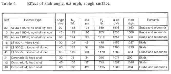
 Effect of Slab Angle, for 6.5 mph (10.4mph km/hr) impacts to a rough surface. Data in Table 4 show that the no-shell helmet gripped the surface at any angle, resulting in long duration neck loading, which did not occur in the hard shell or micro-shell helmets until the concrete slab was at 60 degrees. For the smooth surface concrete impacts in the no-shell helmet, the nylon cover tended to slip off and eliminate the long duration neck loading. However, the pebbles in the rough surface penetrated through the nylon cover into the eps to prevent slippage, thereby resulting in high, long duration neck loading.
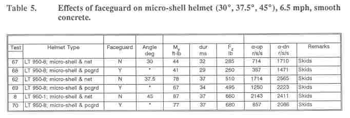
Effect of Faceguard on Micro-Shell Helmet Performance. During the course of previously conducted skid tests [Reference 1 at end], the expensive silicon rubber face of the dummy became abraded from bumping and scraping against the concrete slab subsequent to the initial impact. During those tests it was demonstrated how a clear polycarbonate hockey-type faceguard could be attached to the shell of a hard shell bicycle helmet to eliminate facial rubber damage to the dummy. In this series, tests were conducted to show a faceguard could also be attached to the micro-shell helmet by means of straps anchored to both the shell and 'T' nuts embedded in the nylon net impregnated molded eps liner; that the faceguard could take some significant impacts and scraping but not be torn off the helmet or allow the helmet to rotate on the head; and that a faceguard would protect the dummy's face from abrasion.
In tests during which the dummy face contacted the slab after the initial impact, besides abrading the face the friction caused a rapid change in rotational direction in the head (angular acceleration) and forced the orientation of the neck from extension to flexion. These secondary rotational changes due to facial impact were completely eliminated by the faceguard (compare oscillograms of the third trace from the bottom in Figures c and e, appended). Also, the initial head angular accelerations and the force and bending measurements between head and neck were reduced. The reduction in critical head-neck injury peak measurement on the dummy are tabulated in Table 5 for three comparative impacts of the dummy head wearing a micro-shell helmet with impregnated nylon net, with and without a faceguard.
Many of the retention straps in current use are uncomfortable, complicated for children to adjust properly, and do not maintain the helmet in place, particularly when acted upon by tangential force components. This is at least in part because bicycle helmets are not complete coverage helmets. A chin bearing rear hook-
Page 11
Page 12
up faceguard keeps the helmet in place during impact and makes the helmet more stable during riding. If a bike rider is going to wear a helmet, the faceguard can complete the protective equipment by reducing the risk of: 1) facial injury by abrading plastic instead of facial soft tissue and bone; 2) neck injury by reducing the facial-pavement friction and subsequent twisting, bending, and compression [Footnote a below]; and 3) brain injury by reducing sudden rotational movements during facial impact, and lowering linear head accelerations by absorbing energy by deformation in the event impact occurs on the guard. Figure 4 illustrates the polycarbonate faceguard mounted on the micro-shell helmet at the conclusion of these tests.
Footnote a: The latter can occur in the cervical spine due to body inertia loading, somewhat analogous to the loads on the fifth wheel in a jack knifing semi-trailer.
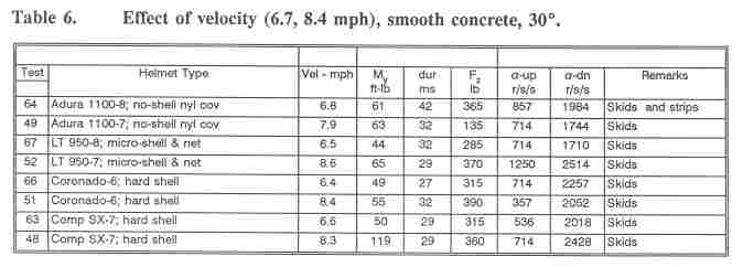
Effect of Velocity Increase on Head-Neck Loads, for smooth concrete at 30 degrees. Data given in Table 6 reveal a general pattern of increased neck loading (My, Fz) with velocity change over the relatively small range of 6.5-8.5 mph (10.4-13.7 km/hr) when hitting the smooth pavement at 30 degrees. This impact attitude produced relatively erratic friction conditions of skidding and skipping along the concrete in all four helmets, at both speeds. This behavior caused erratic angular acceleration changes without a pattern related to velocity, but prevented sustained high neck injury criteria. Past experience indicates that as the speed of impact increases, kinetic energy increases as the speed squared and the potential for injury escalates, especially as the surface angle increases. In a few preliminary trials these effects were found to hold, but it was not possible to increase speeds much above the 6.5 mph (10.4 km/hr) level at higher concrete slab angles without risking damage to the very expensive transducers which resist the head-neck loads in this dummy attitude.
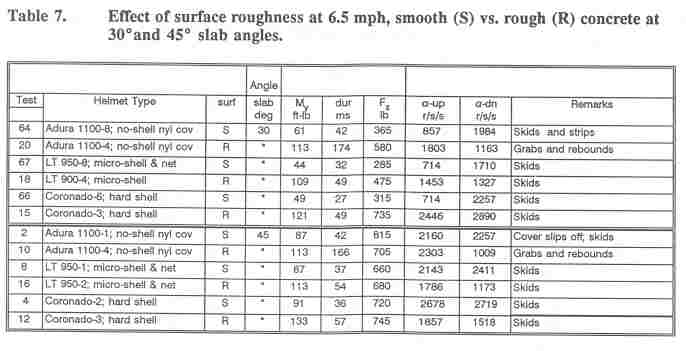
Effect of Surface Roughness at 6.5 mph (10.4 km/hr), smooth v rough concrete, impact at 30 and 45 degree slab angles. It was found that for either of these two angles or surface roughness, the micro-shell and hard shell helmets skid, whereas the cover slips off the no-shell helmet and allows it to slide on its cover only in the
 Page 13
case of the smooth concrete at 30 and 45 degrees. Referring to Table 7, all three helmet types show significantly higher neck bending when impacting the rough concrete as compared to the smooth, but the no-shell helmet rough concrete condition produced much longer high intensity neck loading than the others. The head angular accelerations did not show a pattern related to surface roughness at either angle.
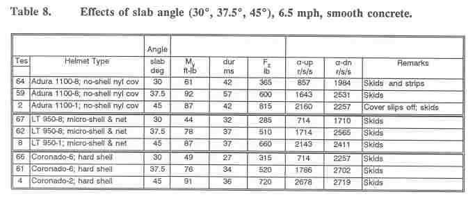
Effects of Slab Angle (30, 37.5, 45 degrees) for smooth concrete impacts at 6.5 mph (10.4 km/hr). For smooth concrete impacts at any of these angles, all three types of helmets skidded. The no-shell helmet skidded on its own nylon cover which was stripped off by the friction between head and pavement. Data obtained for these effects are listed in Table 8. Stripping of the nylon cover was not always a reliable occurrence on the smooth concrete, eg. test 6, Table 1, and did not occur in the case of the rough surface. The pattern for all three types of helmets is a tendency for neck loads and head accelerations to gradually increase as the slab angle increases.
Comparisons of Angle at Which The Three Types of Helmets Gripped the Smooth and Rough Concrete Slabs on Impact at 6.5 mph (10.4 km/hr). The data presented in Table 9 illustrates the angle at which gripping occurred due to impact of the dummy head in body orientation 1 (thorax angle + 17 degrees, neck angle 0 degrees to horizontal), wearing any of the three types of helmets, with rough and smooth concrete at five different slab angles between 30 and 60 degrees. The no-shell helmet with rubber straps gripped the concrete at any angle from 30 degrees and higher, whereas the no-shell helmet with the nylon cover went up to 45 degrees on the smooth concrete before gripping, mainly due to nylon cover release. While not consistent, the nylon cover slipped off and prevented neck load buildup more often than not (see Figure f, appended, for a comparison of no-shell and hard shell oscillograms, equivalent conditions). Rough concrete caused the no-shell helmet to grip at any angle. The micro shell and hard shell helmets performed about equally in beginning to grip at 60 degrees on smooth concrete and 45 degrees for the rough surface. Figure g, appended, shows a comparison of micro-shell and hard shell helmet performances for 6.5 (10.4 km/hr) impact to the smooth concrete slab inclined at 45 degrees.
IV. Conclusions
1. For large tangential component loading of a helmet, which is often likely to occur when a fall from even a slow moving bicycle onto the pavement occurs, hard shell and micro-shell helmets are predicted to be the safest of the four types of helmet outer surfaces tested.2. No-shell helmets with slip-over nylon (or similar material) covers are predicted to be the next most safe helmets in event of a skid-type fall onto a concrete surface. On smooth pavement, the covers are likely to be stripped off and allow skidding to occur, alleviating sustained loading of head and neck.
Page 14
 Page 15
Table 9. Comparisons of angle at which the three types of helmets gripped the smooth and rough concrete slabs on impact at 6.5 mph.

1. Rubber strip covered.
2. Cover pulled off.
3. Micro-shell with net liner skidded until 60 degrees.
4. Rough surface erratic, i.e.: sometimes pebbles come loose and act as ball bearings to promote skid. Comp SX helmet gripped at 45 degrees, but skidded at 52.5 degrees.
3. Rubber strap covered, no-shell helmets similar to that tested are predicted to be the most hazardous of the four helmet types in a skid-type accident. This prediction is based on the hanging-up-on-concrete characteristics displayed in these tests.
2. Cover pulled off.
3. Micro-shell with net liner skidded until 60 degrees.
4. Rough surface erratic, i.e.: sometimes pebbles come loose and act as ball bearings to promote skid. Comp SX helmet gripped at 45 degrees, but skidded at 52.5 degrees.
4. A face shield attached to either a hard or micro-shell helmet is predicted to be the safest equipment for head, neck and face, in the event of a skid-type fall onto the front of the head or face.
5. Results predict that any type of bicycle helmet similar to those used in the helmet drop tests conducted previously [Reference 1 at the end], or in these skid tests, is much more likely to minimize or prevent serious head or neck injury than wearing no helmet, regardless of what kind of head impact occurs in a bicycle crash.
V. Recommendations
1. Bicycle helmets should be covered with either a micro-shell or hard shell to reduce the risk of injury due to 'hang-up' with the pavement in a crash.2. Helmets for children should provide more head coverage and a simpler retention system to improve stability.
Page 16
3. Helmets for children should be equipped with a chin-bearing faceguard for maximum protection of face, head, and neck.
4. Helmet manufacturers should conduct research to devise an appropriate bicycle helmet faceguard for youth and offer it in their line of protective products.
VI. Comment
1. Parents should set an example by always wearing a helmet while riding a bicycle and insist upon their children always wearing a helmet while riding.VII. References
1. Hodgson, V.R.: Impact, Skid, and Retention Tests on a Representative Group of Bicycle Helmets to Determine Their Head-Neck Protective Characteristics. Michigan Department of Public Health, Lansing, Michigan, February 1990.2. Gadd, C.W.: Use of a Weighted - Impulse Criterion for Estimating Injury Hazard; Proceedings of the Tenth Stapp Car Crash Conference, Society of Automotive Engineers, Two Pennsylvania Plaza, New York, NY, 1966.
3. Lowenhielm, P.: Tolerance Level for Bridging Vein Disruption Calculated With a Mathematical Model; Journal of Bioengineering, Vol. 2 pp 501-507, 1978, Pergamon Press, Ltd.
Page 17
Appendix
Figure a. Rubber strap covered no-shell helmet; 6.5 mph impact to smooth slab @ 45 degrees. Characterized by high friction gripping and skipping along slab (see Lz, Lx), prolonged bending moment (My) and axial force (Fz), near injury threshold, lasting approx. 175 ms, as head rolls up slab driven by the body and rebounds. Relatively moderate angular acceleration and very low linear acceleration (Aap Asi).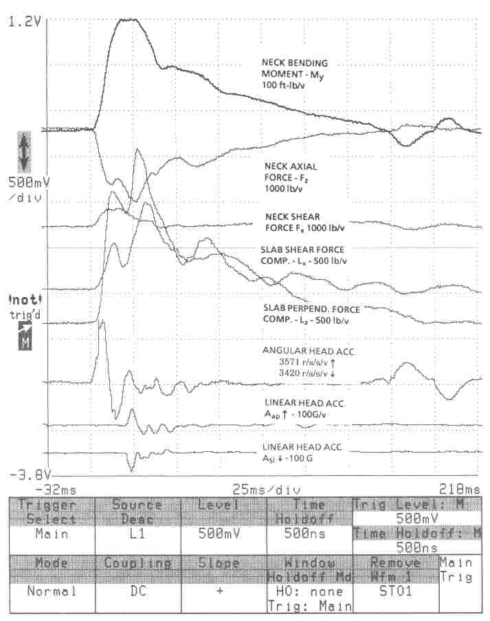 Page 20
Figure b. Nylon covered no-shell helmet; 6.5 mph impact to smooth slab @ 45 degrees. Characterized by initial gripping and then sliding after about 40 ms, as the nylon cover slips off the helmet, so that neck bending (My) and axial force (Fz) are relieved before reaching injury threshold, Moderate angular acceleration and low linear acceleration (Aap,Asi).
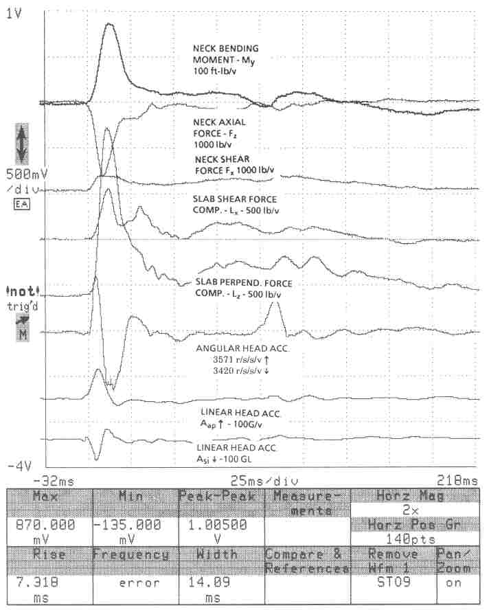 Page 21
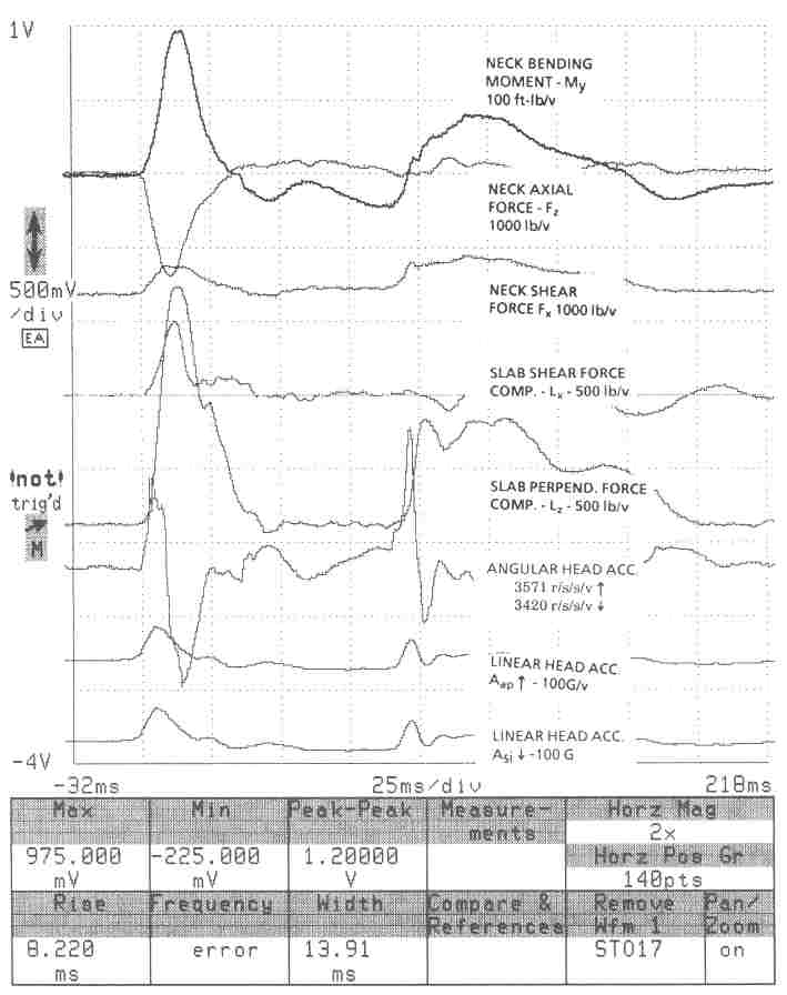
Figure c. Micro-shell helmet; 6.5 mph impact to smooth slab @ 45 degrees. Characterized by initial flexion (My) and Axial Force (Fz) followed by release and landing on face, causing abrupt flexural bending, which in turn causes higher than initial angular acceleration spike. Low linear acceleration (Aap, Asi)
 Page 22
Figure d. Hard shell helmet; 6.5 mph impact to smooth slab @ 45 degrees. Almost identical to micro-shell helmet performance (see Figure c)
 Page 23
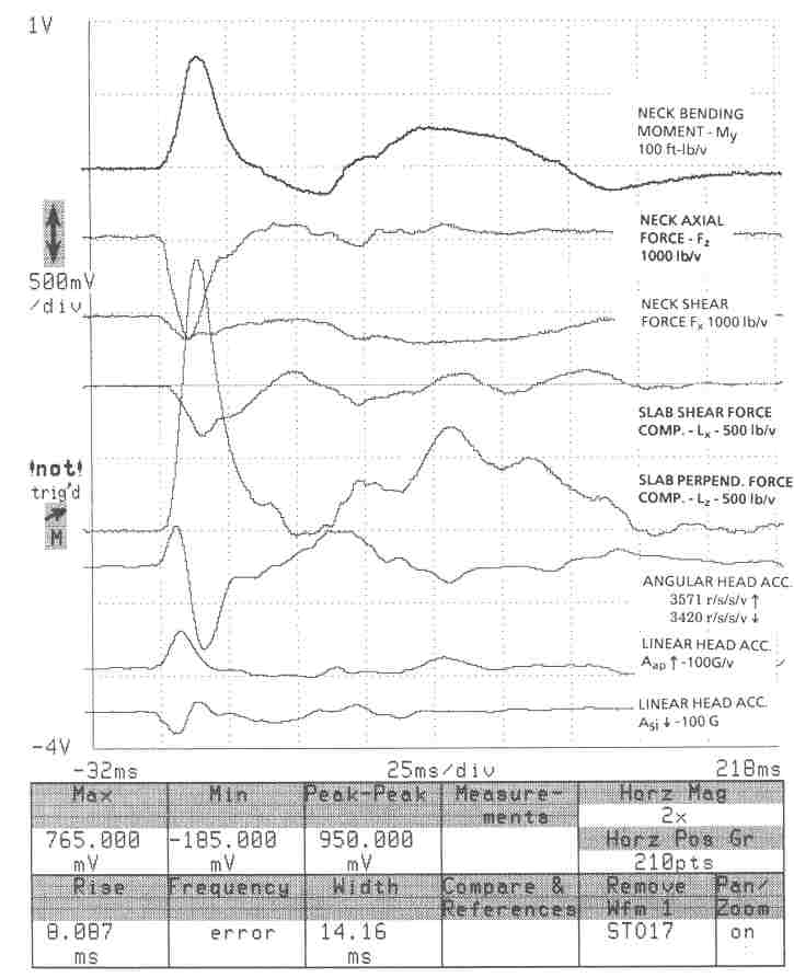
Figure e. Micro-shell helmet with polycarbonate facemask; 6.5 mph impact to smooth slab @ 45 degrees. In comparison to Figure c, micro-shell w.o. guard, the principal difference is the lack of a high secondary angular acceleration which coincides with the abrupt change in flexural bending moment in Figure c, corresponding to when the face of the dummy hit the concrete on the first bounce after impact.
 Page 24
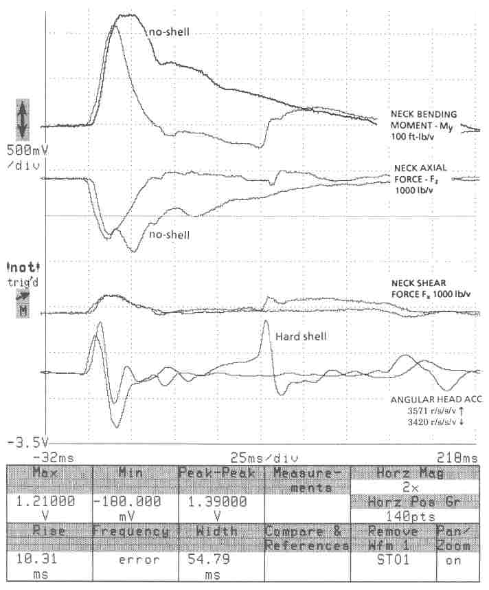
Figure f. No-shell vs hard shell helmet; 6.5 mph impacts to smooth slab @ 45 degrees. The principal difference in the dummy head-neck transducer measurements shows up as a much more prolonged bending (My) and axial compression force (Fz) neck loading, when the no-shell helmet gripped the concrete and rebounded, whereas the hard shell helmet bounced off the concrete and landed on the face, causing a secondary angular head acceleration because of momentary gripping of the concrete by the face before skidding.
 Page 25
Figure g. Micro-shell vs hard shell helmet; 6.5 mph impacts to smooth slab @ 45 degrees. The instrumentation signatures of the two types of helmets were similar for smooth concrete impact cases, but with some variation for rough concrete impacts, which produced the least consistent results of the two surfaces.
 Page 26
(end of study)
Posted on the web in April, 2002
Back to the top
Back to the Home Page